详细介绍
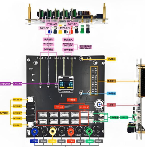
The relationship between power module wiring method and output power
As the energy supply core of electronic devices, the power module has a close relationship between its wiring method and output power. Understanding and mastering this relationship is of great significance for optimizing the performance of electronic devices and improving energy efficiency.
Firstly, let's take a look at the basic series connection method. In some cases, multiple power modules may be connected in series to increase the output voltage. However, this approach requires attention to the consistency and voltage resistance of the power module. If the output voltage of the series connected power modules is inconsistent, it may cause the modules with higher voltage to bear larger loads, thereby affecting their lifespan and output power stability. Moreover, the total output current after series connection is usually limited by the module with the minimum output current, as the current is equal everywhere in the series circuit. In addition, series connection may also increase line resistance, resulting in additional power loss.
Let's take a look at the parallel connection method again. Parallel connection of multiple power modules is to increase output current and thus improve output power. But when connecting in parallel, it is necessary to ensure that the output voltage of each power module is the same, otherwise there will be current imbalance. For example, modules with slightly higher output voltage may output larger currents, while modules with lower output voltage may output smaller currents or even experience current backflow, which not only affects output power but may also damage the power module. In order to achieve current sharing in parallel modules, some special circuit designs can be used, such as series resistance method, diode parallel method, current sharing parallel method, etc. The series resistance method limits current by connecting resistors of appropriate resistance values in series at the output terminals of each module, but it increases system power consumption; The diode parallel method uses diodes to prevent current backflow and also to balance the current to a certain extent; The current sharing parallel method uses specific current sharing ICs to design power supply parallel outputs, which can achieve accurate current sharing control, but the cost is relatively high.
Taking switch mode power supplies as an example, when multiple switch mode power supplies are connected in parallel, attention should also be paid to issues such as cable length and interface protection. Inconsistent cable lengths can cause impedance changes and voltage drops, affecting the stability of the output. And the protection of the docking cable interface is to prevent arc light caused by loose joints under high power, high voltage, and high current, as well as to avoid problems such as poor contact of joints and aging of insulation materials, which may lead to a decrease in output power or safety hazards.
