详细介绍
例如,在自动化生产线上的机械臂,若机械臂在启停时振动明显,可通过调节液压缓冲器的缓冲力,使其运行更加平稳。但在调节过程中,可能会出现缓冲器漏油的情况,这可能是密封件损坏或调节部件未拧紧导致,需及时检查密封件并拧紧调节部件。
Detailed explanation of hydraulic buffer adjustment method
In modern industrial production and mechanical equipment operation, hydraulic buffers effectively reduce equipment wear caused by impact and ensure stable operation due to their excellent buffering performance. Understanding and mastering the adjustment methods of hydraulic buffers is crucial for improving equipment performance and service life.
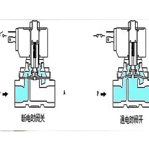
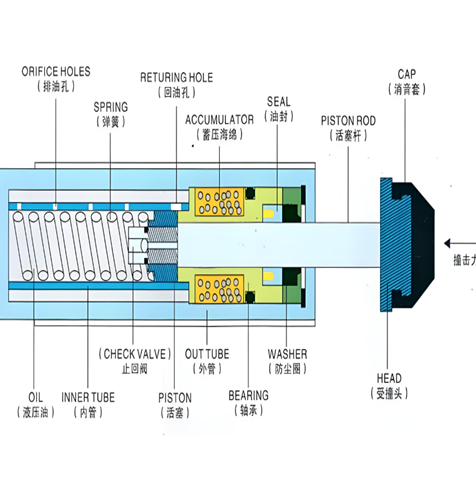
The hydraulic buffer is mainly composed of piston rod, piston, oil storage chamber, throttle hole and other components, and its working principle is based on the flow characteristics of hydraulic oil. When the equipment is impacted, the piston rod is compressed, pushing the piston to move in the oil storage chamber. Hydraulic oil flows from the high-pressure chamber to the low-pressure chamber through the orifice, generating resistance and achieving buffering. The size of the throttle hole directly affects the flow rate of hydraulic oil, which in turn determines the magnitude of the buffering force.
When adjusting hydraulic buffers, the first step is to clarify the buffering effect required for equipment operation. If the buffering force is too small, the equipment will still produce significant vibration under impact; Excessive buffering force may affect the normal operating speed of the equipment. The adjustment steps are as follows: turn off the power source of the equipment to ensure the safety of the adjustment process; Find the adjustment component of the buffer, usually the adjustment screw or knob; Rotate the adjusting component clockwise to reduce the throttle hole and increase the buffering force; Rotate counterclockwise, the throttle hole becomes larger, and the buffering force decreases. During the adjustment process, the adjustment amplitude should not be too large each time. After adjustment, a trial run should be conducted to observe the operating status of the equipment. Multiple adjustments should be made according to the actual situation until the desired buffering effect is achieved.
For example, in an automated production line, if the robotic arm vibrates significantly during start stop, the buffering force of the hydraulic buffer can be adjusted to make its operation smoother. However, during the adjustment process, there may be oil leakage from the buffer, which may be caused by damaged seals or loose adjustment components. It is necessary to check the seals in a timely manner and tighten the adjustment components.